PCB Assembly
Keg Cop runs on an ESP32 controller. To detect the information to be logged, you need to connect specific devices to the controller. I have provided a main circuit board design, as well as several breakouts for your use.
Assembly is not difficult, but it does require some basic soldering.
Materials Required
This project uses widely-available and inexpensive components. You may find you are better off buying a resistor assortment, for instance, or buying 10 or 20 of a piece at a time for a nominal cost from China. You will need to order the printed circuit boards from a supply house. The heart of the system is, of course, the controller.
Because there are multiple ways to configure this Keg Cop system, I will demonstrate using my single Kegerator, three taps, and a temperature control setup. Other configurations may be detailed on the planning page.
Gather the following parts and pieces to get started:
Controller
The ESP32 controller is paired with many different “developer boards” to make connections easier. While you can buy a bare ESP32 chip, you will walk that road alone.
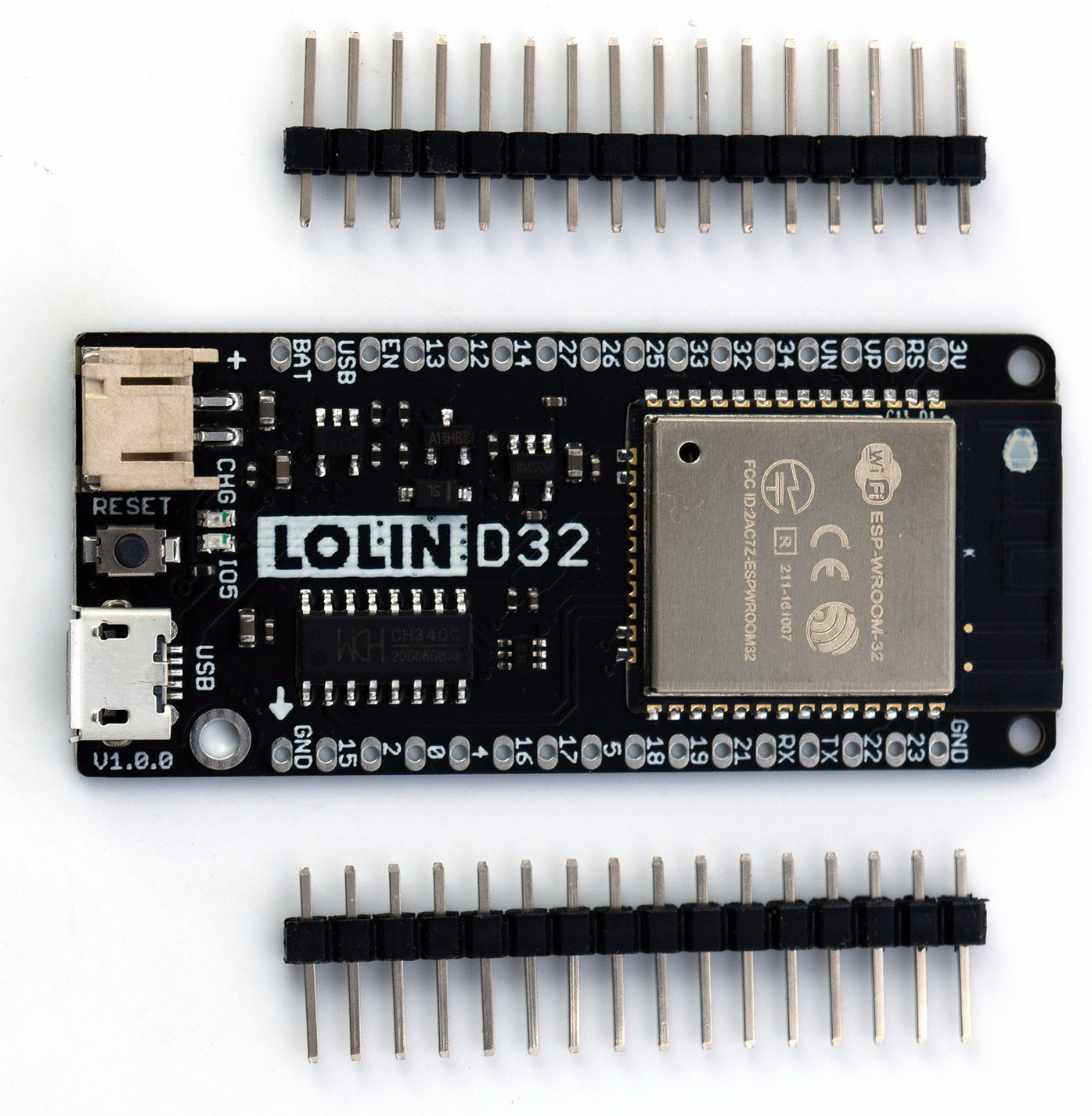
The developer board used in this project is the Lolin D32 v1.0.0 (not the Pro or 2.0.) Wherever you purchase it, make sure it is an official Espressif ESP32-WROOM-32 Module. It says 4MB (or sometimes shown as 32Mb, which is 4 megaBYTES converted to megaBITS.) There is a version sometimes called “LED,” which means there is an annoying blinking LED when a battery is not connected. It will work, and so long as it’s in a case, you won’t notice the blinking. Be sure it comes with the 16-pin male and female headers, or get them elsewhere. It is common to only receive the male headers in the package.
You can find the Lolin D32 in many places. Lolin D32 is one of maybe hundreds of development boards. Their prime delivery method to hobbyists seems to be the Lolin store on AliExpress.
AliExpress also seems to be the least expensive path, but of course, ordering direct from China does take a bit longer than other methods. You will spend more but get your hands on the device quicker if you purchase from Amazon or any other place you can find it.
Printed Circuit Boards
This configuration will use the following three boards:
The links will take you to OshPark where I have uploaded the designs. OshPark is not the cheapest, but they are the most consistent fab house I have dealt with. You’re only talking the difference of a few dollars in your project between them and other fab houses. For my peace of mind, and for me to recommend them to you, I think it’s worth it. You may take the files from GitHub and upload them yourself somewhere else to save money if you choose.
Components
For this configuration, we will use the following components:
Main Board:
2 x 2.54mm Pitch Single Row Female 16P PCB socket Board Pin Header Connector Strip Pinheader 2/3/4/6/10/12/16/20/40Pin For Arduino (D32) (Note: Multiple items on the page, be sure to select the proper item)
2 x 0.1μF (1.0nF) Ceramic Capacitor (102) 2.54mm spacing (C1, 3) (Note: The same link as below, select the proper item)
2 x 1.0μF Ceramic Capacitor (105) 2.54mm spacing (C2, C4) (Note: The same link as above, select the proper item)
*1 x DS18B20 PCB-mount sensor (IC1) (Note: Multiple items on the page, be sure to select the proper item)
14 x 2.2kΩ 1/4W 5% Axial Resistor (R1-R5) (Note: Multiple items on the page, be sure to select the proper item)
1 x 2-pin Straight Male Header (POWER) (Note: More than enough in one lot for all three headers)
*1 x 3-pin Straight Male Header (ROOM) (Note: More than enough in one lot for all three headers)
1 x 4-pin Straight Male Header (RELAY) (Note: More than enough in one lot for all three headers)
If you want the convenience of one-click ordering from the US, the BOM for the main board parts (not the PCB itself) may be purchased from Mouser. This does not include the DS18B20 temperature sensor.
Sensor Board:
*4 x DS1820 Stainless steel package Waterproof DS18b20 temperature probe (Note: Multiple items on the page, be sure to select the proper item)
If you want the convenience of one-click ordering from the US, the BOM for the sensor board (not the PCB itself) may be purchased from Mouser. This does not include the DS18B20 temperature sensors.
Daisy Chain Boards (per flowmeter, multiply all numbers x 3 for three flowmeters):
If you want the convenience of one-click ordering from the US, the BOM for the daisy-chain board (not the PCB itself) may be purchased from Mouser. You will need one of this list per flowmeter.
(*) - Optional items for use when you desire a room temperature sensor. Either use a DS18B20 sensor with a lead or a PCB-mount sensor - the sensor on a lead is recommended to avoid invalid readings due to heat from the controller.
Soldering
You are going to have to solder. If you have legitimately never soldered anything before, I recommend you spend a few minutes on YouTube and watch a few videos. Sparkfun also has a very nice tutorial. It is not hard at all once you get the hang of it. And, while the boards are comparatively small, the components chosen are simple through-hole parts, which may be easily soldered by a beginner with a little patience.
Be sure to use flux when you solder. Liquid flux is the easiest to use. Be sure to get both sides of the board because you want the solder to flow to both sides. After you solder from behind, flip the board over to make sure you get a good flow. If not, you can always touch up from the top (but don’t tell anyone you cheated.)
I do not intend to provide a step-by-step on how to solder here. Still, I recommend the following part installation order for ease of assembly:
Resistors - These are the shortest mounted components. Soldering the resistors to the board first is the least challenging. They are also some of the most heat-tolerant parts, so these grant you some experience to get you going.
Capacitors - The next tallest components, these should go on next. They are also relatively tolerant of heat, so you can continue to refine your skills. Be sure to get them as close to the board as possible since having them stick up changes their intended impact on the circuit.
DS18B20 Sensor - Now that you are sure of your skills, this sensor should be soldered next if you use one. Be careful not to overheat the device, but they are not too sensitive.
Pin headers and terminal blocks - These components are not vulnerable to the heat at all except for the plastic.
RJ45 Jacks - These are the tallest items, and you should solder them on last.
When you solder the sensor board, you have a choice. I designed it to orient the 3-pin terminal block’s openings pointing in to route the cables together out one end of a case. You may reverse them if you prefer.
Once you have finished soldering the shield, make sure to clean off the flux. You can use cheap vodka or Everclear, or a commercially available flux solvent.
Modifications
The pcb directory in the repository contains the Eagle files for the printed circuit board shield supporting Keg Cop. You can download the design files, modify them, and upload them to the PCB manufacturer of your choice. If you would like to personalize these board designs, you may edit them with Autodesk’s EAGLE. EAGLE is a scriptable electronic design automation (EDA) application with schematic capture, printed circuit board (PCB) layout, auto-router, and computer-aided manufacturing (CAM) features. EAGLE stands for Easily Applicable Graphical Layout Editor and is developed by CadSoft Computer GmbH.